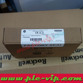
Category: PLCs, Power Supplies & I/Os
Manufacturer: Rockwell
Group: PLC Automation
The 1756-IB16ISOE (also written 1756IB16ISOE) is the sequence-of-events input module: 16 inputs with a 10...55 V DC operating range — the widest of the DC input family — at 5.1 mA maximum input current and 320 mA at 5.1 V DC / 2 mA at 24 V DC backplane load (1756-IN062).
The 10...55 V DC range is the headline. It covers the standard 24 V DC field supply and also 48 V DC control circuits, so a plant that runs 48 V DC for older equipment does not need a separate input module type. No other IB module in the published table spans both.
Isolation is 250 V continuous basic from inputs to backplane and 125 V basic input-to-input — note that the input-to-input figure is 125 V here, against 250 V on the IB16IF. The lower figure is a real difference, not a typo, and it matters when two field circuits at different potentials share one module.
The 320 mA backplane draw is the highest of the DC input modules: the sequence-of-events function — time-stamped capture of input transitions — lives on the backplane side. In a chassis, that cost has to be counted per module.
1756-IB16 | 16 sinking inputs, 10...31.2 V DC 10 mA, backplane 100 mA, UPC 612598171293 | In stock |
1756-IB16D | 16 diagnostic inputs, 10...30 V DC 13 mA, backplane 150 mA | In stock |
1756-IB16I | 16 isolated inputs, 10...30 V DC 10 mA, backplane 135 mA | In stock |
1756-IB16IF | 16 fast peer-control inputs, 10...30 V DC 5 mA, backplane 275 mA | In stock |
1756-IB16ISOE | 16 sequence-of-events inputs, 10...55 V DC 5.1 mA, backplane 320 mA | In stock |
1756-IB32 | 32 sinking inputs, 10...31.2 V DC 5.5 mA, backplane 120 mA, UPC 612598171309 | In stock |
1756-IC16 | 16 inputs, 30...60 V DC, backplane per 1756-IN062 | In stock |
1756-IG16 | 16 TTL inputs, backplane per 1756-IN062 | In stock |
1756-IV16 | 16 inputs, 48 V DC, backplane per 1756-IN062 | In stock |
Application | Discrete input |
Brand Name | Rockwell (Rockwell) |
Cat Num | 1756-IB16ISOE |
Communication | Backplane (producer/consumer) |
Display | — |
Enclosure | None (open-style) |
Interface | Removable terminal block |
Mounting | Chassis slot |
Number Of Channels | 16 |
Standard | CE, UL, CSA, RCM |
Sub Brand | ControlLogix |
Type | Digital Input Module |
UNSPSC | — |
Attribute values above are reproduced from the manufacturer's product data. For the authoritative technical record see Rockwell publications 1756-TD003 (module specifications) and 1756-IN062 (DC digital I/O installation instructions). Certification details, with certificate and file numbers, are listed in the FAQ below.
Where the module sits in a typical system
Sequence-of-events capture is for fault analysis: which input changed first when a line tripped, to what accuracy, in what order. The module records transitions with time stamps so the answer does not depend on the controller scan.
The 10...55 V DC window makes it the practical choice for mixed-voltage panels — 24 V DC sensors and 48 V DC legacy circuits on the same rack — provided the 125 V input-to-input isolation is acceptable.
Because the field burden is 5.1 mA, it also suits long sensor runs where cable capacitance and leakage would otherwise degrade a 24 V signal.
Commissioning in five steps
- Key the removable terminal block to the module before wiring. Rockwell's DC digital I/O instructions include keying as a step, and a wrongly keyed block will not seat.
- Wire to conductor category 1 and keep the field wiring separated from the analogue and communication classes in the panel (1770-4.1).
- Check the sinking or sourcing convention against the field device before terminating. The IB family is sinking input; a sourcing sensor wired as if it were sinking gives a channel that never turns on.
- Verify the input voltage range against the actual field supply, not against the nominal 24 V. 10...31.2 V DC on the IB16 means a 32 V rail is outside the published range.
- Set the module's input filter and change-of-state configuration in the Logix Designer project before commissioning, so the first fault report is not a filtering artefact.
Diagnostics: status indicators
Three bi-colour indicators plus the alphanumeric display cover almost every commissioning fault, so most problems are resolved at the panel without a laptop.
| Indicator | State | Meaning and first action |
| Check 2 | 125 V input-to-input | Not 250 V. Where two circuits at different potentials share the module, that figure decides the design. |
| Check 3 | 320 mA backplane | The highest of the DC input family. Four modules in a chassis draw 1.28 A at 5.1 V DC. |
| Check 4 | 5.1 mA field burden | Low enough for two-wire sensors, and much lower than the 10 mA of the standard IB16. |
| Check 5 | Timestamping is a project setting | The sequence-of-events behaviour is configured in Logix Designer; without that configuration the module behaves as a fast input. |
Specifications per Rockwell publication 1756-IN062 (ControlLogix DC Digital I/O Modules installation instructions); module behaviour per 1756-UM058 and technical data 1756-TD002 and 1756-IN050.
Replacing a 16-point input module of an earlier generation
The standard module is 1756-IB16: 10...31.2 V DC, 10 mA, 100 mA backplane.
The fast peer-control module is 1756-IB16IF: 10...30 V DC, 5 mA, 275 mA backplane, 250 V input-to-input.
The 90...140 V DC variant for higher-voltage DC circuits is 1756-IH16ISOE, with its own derating table in 1756-IN062.
Which ControlLogix EtherNet/IP module to specify
- 1756-IB16 — 16 sinking inputs, 10...31.2 V DC, 10 mA max, backplane 100 mA at 5.1 V DC, reinforced isolation to the backplane.
- 1756-IB16D — the diagnostic version, 10...30 V DC, 13 mA max, backplane 150 mA at 5.1 V DC, basic isolation.
- 1756-IB16I — individually isolated inputs, 10...30 V DC, 10 mA max, backplane 135 mA at 5.1 V DC, isolation input-to-input.
- 1756-IB32 — 32 sinking inputs in one slot, 10...31.2 V DC, 5.5 mA max, backplane 120 mA at 5.1 V DC.
- 1756-IB16IF — fast peer-control input module, 10...30 V DC, 5 mA max, backplane 275 mA at 5.1 V DC.
- 1756-IB16ISOE — sequence-of-events input, 10...55 V DC, 5.1 mA max, backplane 320 mA at 5.1 V DC.
- 1756-TBNH / 1756-TBSH — the removable terminal block housings; the module needs one and it is ordered separately.
FAQ — 1756-IB16ISOE ControlLogix Sequence of Events Input | Rockwell
What is the 1756-IB16ISOE?
A 16-point sequence-of-events DC input module with time-stamped input capture, 10...55 V DC, 5.1 mA maximum input current.
What is the backplane current?
320 mA at 5.1 V DC and 2 mA at 24 V DC — the highest of the DC input modules in 1756-IN062.
Can it take 48 V DC?
Yes. The published range is 10...55 V DC, which covers 24 V and 48 V DC control circuits.
What isolation does it provide?
250 V continuous basic inputs-to-backplane and 125 V basic input-to-input.
Why is input-to-input 125 V here?
The published table gives 125 V for this module against 250 V for the 1756-IB16IF; use the printed figure for the module you are installing.
What does sequence of events mean?
Each input transition is captured with a timestamp, so event order can be reconstructed independently of the controller scan.
Does it need configuration?
Yes — the sequence-of-events behaviour is configured in the Logix Designer project.
What documents cover it?
1756-IN062 for installation and specifications, 1756-TD002 for technical data and 1756-UM058 for the user manual.
Data sources. Technical values on this page come from Rockwell publications 1756-TD003 (ControlLogix Communication Modules Specifications), 1756-IN050 (1756 EtherNet/IP Communication Modules, installation instructions), 1756-UM004 (ControlLogix EtherNet/IP Network Devices User Manual) and the manufacturer's product page for 1756-IB16ISOE. Values re-checked 15 November 2026.