Category: PLCs, Power Supplies & I/Os
Manufacturer: Rockwell
Group: PLC Automation
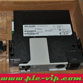
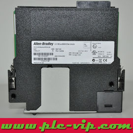
The 1756-L62S (also written 1756L62S) is the 4 MB member of the GuardLogix 5560 range: a ControlLogix controller with a safety task, used as a pair with the 1756-LSP safety partner in the slot immediately to its right. The pair reaches SIL CL 3 / PL e / Category 4 with a single project holding both the safety and the standard logic (1756-TD001I Tables 14 and 18).
Memory is 4 MB of user memory plus 1 MB of safety memory, with 478 KB of I/O memory and a 128,000 digital / 4,000 analogue I/O ceiling. Current draw is 1200 mA at 5.1 V DC and 14 mA at 24 V DC per module, 3.5 W and 11.9 BTU/hr, isolation 30 V continuous basic insulation type tested at 720 V DC for 60 s. Redundancy is not supported, and the published supply list for the L6xS pair is the standard set — 1756-PA72, PA75, PB72 or PB75.
Application | Safety Control (SIL 3 / PL e) |
Brand Name | Rockwell (Rockwell) |
Cat Num | 1756-L62S |
Communication | Backplane (EtherNet/IP, ControlNet, DeviceNet) |
Display | Indicators (OK, RUN, I/O, FORCE, BATTERY, RS-232) |
Enclosure | None (open-style) |
Interface | 1 RS-232 serial port |
Mounting | Chassis |
Number Of Channels | 1 |
Standard | CCC,CE,CSA,C-TICK,CUL,GOST,KC,MARINE,NRTL,RCM,UL
Vendor attribute list — the current Rockwell certification record, with certificate and file numbers, is in the FAQ. |
Sub Brand | ControlLogix |
Type | Safety Controller |
UNSPSC | 32151705 |
Attribute values above are reproduced from the manufacturer's product data. For the authoritative technical record see Rockwell publications 1756-TD003 (module specifications) and 1756-RM093 (GuardLogix safety reference manual). Certification details, with certificate and file numbers, are listed in the FAQ below.
Where the module sits in a typical system
4 MB of standard memory with 1 MB of safety memory is the usual shape of a packaging or assembly cell: a safety program of guarding and interlock logic that stays well inside 1 MB, and a standard program large enough for recipes, sequencing and HMI tag exchange.
The design constraint that decides the pair is the safety network, not the memory: EtherNet/IP, ControlNet or DeviceNet for standard and safety communication, with Guard I/O modules on the field side. Redundancy is not an option on this family.
Commissioning in five steps
- Install the primary controller and the 1756-LSP safety partner as a pair: the partner goes in the slot immediately to the right of the primary, and the pair occupies two slots. A single controller in a chassis does not run the safety task.
- The safety partner is configured automatically — no IP address, no project of its own. The safety logic is in the primary controller's project, in a safety task that is set to its integrity level.
- Budget the chassis against 1200 mA at 5.1 V DC plus 14 mA at 24 V DC for each of the two modules, and check that the supply is one from the published list: 1756-PA72, PA75, PB72 or PB75.
- Read the safety status before validating: the project reports a safety-task signature and a partner status, and a missing or mismatched partner is a configuration fault, not a field-device fault.
- Lock and protect the safety memory only after the safety task has been functionally tested; once locked, the safety logic cannot be edited and the SIL 3 claim applies.
Diagnostics: status indicators
Three bi-colour indicators plus the alphanumeric display cover almost every commissioning fault, so most problems are resolved at the panel without a laptop.
| Indicator | State | Meaning and first action |
| OK | Red | Major fault or self-test failure; check the safety task status before any restart. |
| RUN | Green solid | Program running, standard and safety tasks executing. |
| RUN | Red | Major fault latched; the program is stopped. |
| I/O | Green solid | All configured I/O modules are communicating. |
| I/O | Flashing green | One or more configured modules are not responding. |
| FORCE | Amber | Forces enabled in the standard task — a live wiring check is not valid while this is lit. |
| BATTERY | Red | Battery low or missing; the project in RAM is not protected across a power cycle. |
| Partner status | Per project | The safety partner is reported in the project: a missing or mismatched partner stops the safety task from validating. |
| RS-232 | Green flashing | Serial activity on the programming port. |
Indicator behaviour per Rockwell publication 1756-UM020 (GuardLogix Controllers User Manual) and 1756-IN050.
Replacing a 1756-ENBT
This is a 5560-family part and the family is discontinued; the migration target is the GuardLogix 5570 pair 1756-L71S + 1756-L7SP, or the 5580 safety controllers where the chassis is being rebuilt. The safety partner changes with the family, so the pair is replaced as a pair.
Budget the migration as validation work as well as hardware: the safety task is re-created against the new controller, the safety signature regenerates, and the functional test is repeated before the cell is released.
Which GuardLogix safety controller to specify
- 1756-L61S + 1756-LSP — 2 MB user memory, 1 MB safety memory. Smallest GuardLogix 5560 pair.
- 1756-L62S + 1756-LSP — 4 MB user memory, 1 MB safety memory.
- 1756-L63S + 1756-LSP — 8 MB user memory, 3.75 MB safety memory. The largest 5560 safety pair; the one most SIL 3 cells were built around.
- 1756-LSP — the safety partner; it is not a spare of the primary controller and cannot be used on its own.
- 1756-L7xS + 1756-L7SP — the GuardLogix 5570 pairs, 2 to 8 MB user and 1.5 to 4 MB safety memory.
FAQ — GuardLogix 1756-L62S / 1756L62S 4 MB Safety Controller
How does the 1756-L62S differ from the 1756-L61S?
Standard user memory only — 4 MB against 2 MB. Safety memory is 1 MB on both, and the RS-232 port, 250 connection behaviour, two-slot footprint, 1200 mA draw and 3.5 W dissipation are the same across the L6xS pair (1756-TD001I Table 18).
What safety rating does the pair carry?
SIL CL 3 per IEC 61508/EN 62061 and Category 4 / PL e per EN ISO 13849-1, used as described in publication 1756-RM093. TÜV holds the functional-safety certification and UL certifies SIL CL 3 under file E256621 (Table 20).
Which partner module does it need?
The 1756-LSP, installed in the slot immediately to the right of the primary controller. The partner is configured automatically and carries the same safety memory as its primary controller — 1 MB in this case.
What is the current draw of the pair?
1200 mA at 5.1 V DC and 14 mA at 24 V DC for each of the two modules, 3.5 W and 11.9 BTU/hr each (Table 18). A pair therefore appears twice in the chassis power budget.
Is a redundant GuardLogix 5560 system possible?
No. Table 14 records controller redundancy as not supported for GuardLogix controllers, so a SIL-rated cell on this family is a single pair, not a redundant pair.
Which programming languages are allowed in the safety task?
Relay ladder with the safety application instructions only. The standard task keeps the full Logix set — ladder, structured text, function block diagram and sequential function chart.
What are the environmental limits and certifications?
Operating 0…60 °C, storage -40…85 °C, 5…95% RH non-condensing, 2 g vibration at 10…500 Hz, 30 g and 50 g shock, CISPR 11 Class A, ESD 6 kV contact and 8 kV air, radiated RF 10 V/m 80…2000 MHz and 3 V/m 2000…2700 MHz, EFT ±4 kV at 5 kHz and surge ±2 kV line-earth (Table 19). Certifications: c-UL-us UL E65584/E194810, CSA LR54689C/LR69960C, CE 2004/108/EC and 2006/42/EC, C-Tick/RCM, FM Class I Division 2, KC, plus the TÜV and UL functional-safety listings (Table 20).
Which chassis accept the pair?
1756-A4, A7, A10, A13 or A17, any slot, with the pair occupying two slots side by side. Power supply from 1756-PA72, PA75, PB72, PB75; wire category 2 applies on the RS-232 port and the temperature code is T4A.
Data sources. Technical values on this page come from Rockwell publications 1756-TD001 (ControlLogix and GuardLogix Controller Specifications) and 1756-RM093 (GuardLogix Controller Systems Safety Reference Manual) and the manufacturer's product page for 1756-L62S. Values re-checked 15 November 2026.