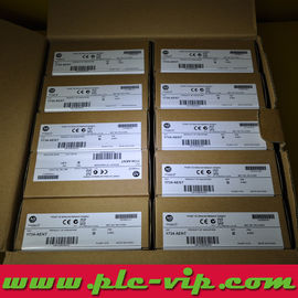
POINT I/O 1734-OE2C / 1734OE2C 2-Channel Analog Current Output Module
Category:
PLCs, Power Supplies & I/Os
Manufacturer:
Rockwell
Group:
POINT I/O Analog Output
The 1734-OE2C drives two 4...20 mA or 0...20 mA outputs from a POINT I/O slice with 13-bit resolution over the 0...21 mA span - 2.5 µA per count - onto a load of 0 to 750 Ω.
When the module powers up before the controller establishes communication it holds 0 mA, not the last value, so a valve or damper driven from this output goes to its de-energised position on a network loss. That behaviour belongs in the safety review, not in a footnote.
Product Specifications 1734-OE2C (PDF)
Number of outputs |
2 single-ended, non-isolated, current |
Resolution |
13 bits over 0...21 mA, 2.5 uA/count average (typical 2.3...2.7 uA/count) |
Output current range |
4...20 mA or 0...20 mA, user configurable |
Output at power-up |
0 mA until communication is established |
Resistive load |
0...750 ohm |
Accuracy drift with temperature |
30 ppm/deg C |
Step response to 63% of full scale |
24 us |
Conversion rate |
16 us |
Power dissipation, max |
1.23 W with 750 ohm load on each output, 1.83 W with 0 ohm load |
Thermal dissipation, max |
4.19 BTU/hr at 750 ohm, 6.24 BTU/hr at 0 ohm |
External DC supply |
24V DC nominal, 10...28.8V DC, 70 mA at 24V DC including 20 mA outputs |
Data image |
Produces 2 bytes of input data and fault status, consumes 4 bytes of output data |
Field wiring terminations |
0/1 - output 0/1, 2/3 - chassis ground, 4/5 - common, 6/7 - 24V DC supply |
Data format |
Signed integer |
Absolute accuracy |
0.1% full scale @ 25 °C, including offset, gain, non-linearity and repeatability |
Terminal base |
1734-TB, 1734-TBS, 1734-TB3, 1734-TB3S, 1734-TOP or 1734-TOPS |
Terminal base screw torque |
0.6 Nm (7 lb-in) |
Keyswitch position |
4 |
Indicators |
1 module status, 1 network status, 2 output status (green/red) |
POINTBus current, max |
75 mA @ 5V DC |
Isolation voltage |
50V continuous, tested 2200V DC for 60 s, no isolation between channels |
Dimensions, HxWxD |
56 x 12 x 75.5 mm |
Weight, approx |
36 g |
Wire size |
0.25...2.5 mm2 (22...14 AWG) copper rated 75 °C or greater, 1.2 mm insulation max |
Operating temperature |
-20...55 °C |
Attribute values above are reproduced from the manufacturer's product data. For the authoritative technical record see Rockwell publications 1734-OE2C installation instructions (module specifications) and 1734-SG001E-EN-P (installation instructions). Certification details, with certificate and file numbers, are listed in the FAQ below.
0 mA at power-up is the designed state
The specification reads 0 mA output until communication is established. On a cable break, an adapter reset or a controller download the loop current falls to zero, which usually means a closed valve or a minimum-speed drive. If the process needs last-value hold or a specific failsafe current, that has to be built in the controller or with a signal conditioner - the module cannot be configured to do it.
Loop burden: 0 to 750 ohm
750 Ω at 20 mA is 15V of burden, which sets how many series devices a single output can drive. Two 250 Ω receivers plus 100 Ω of cable is already 600 Ω; adding a third drops the loop out of range. The power dissipation also rises at low burden - 1.83 W at 0 Ω against 1.23 W at 750 Ω - so a shorted output is the hot case, not the loaded one.
13 bits is enough for a valve, not for a lab
2.5 µA per count over 4...20 mA gives about 6,400 counts, 0.016 mA of resolution. A control valve with 0.1% positioning needs 1,600 counts, so the module is adequate; a calibrated 4-wire transmitter simulator is not what this output is for.
Step response and conversion rate
24 µs to 63% of full scale and a 16 µs conversion rate mean the electrical output is effectively instantaneous. The speed limit in the loop is the controller task and the valve, not the module - which is why a fast PID on this output is limited by the scan, not by the D/A.
Data image and wiring
The module produces two bytes of input data plus fault status and consumes four bytes of output data. Terminals 0 and 1 are the outputs, 2 and 3 chassis ground, 4 and 5 common and 6 and 7 the 24V DC field supply; external supply current is 70 mA at 24V DC including both outputs at 20 mA.
FAQ — 1734-OE2C
What does 1734-OE2C output before the controller connects?
0 mA. The specification states 0 mA output until communication is established, so the loop drops to zero on a network loss or module reset rather than holding the last value.
What load can the current output drive?
0 to 750 ohm resistive. At 20 mA that is up to 15V of burden, and power dissipation rises as burden falls - 1.83 W at 0 ohm against 1.23 W at 750 ohm.
What is the resolution and accuracy?
13 bits over 0...21 mA, 2.5 uA per count (typically 2.3...2.7 uA), with 0.1% of full scale accuracy at 25 deg C and 30 ppm/deg C drift.
Which ranges can be configured?
4...20 mA or 0...20 mA, user configurable, unipolar only. The output is current; for a voltage signal use 1734-OE2V.
Does the module need external 24V DC?
Yes, 10...28.8V DC with 24V DC nominal, drawing 70 mA at 24V DC including both outputs at 20 mA. Field supply enters at terminals 6 and 7 and the common at 4 and 5.
Are the two output channels isolated?
No. Field to system is 50V continuous, tested at 2200V DC for 60 s, with no isolation between the individual channels.
Data sources. Technical values on this page come from Rockwell publication 1734-IN027 series installation instructions for the 2-channel analog output modules (1734-OE2C, 1734-OE2CK, 1734-OE2V, 1734-OE2VK, Series C), 1734-SG001E-EN-P (POINT I/O Modules Selection Guide, March 2013) for 1734-OE4C and 1734-UM001. Any attribute the publication does not print is marked Not published rather than taken from a distributor page. Catalog number, packaging and stock status are the stock record of this listing.